Figure 2.7)
If a wheel or a crank is mounted coaxially to a pivot in some mechanism, it does not matter how the object is mounted physically. In a bicycle, the rear wheel could be physically mounted to the seat stay or chain stay, and the crank could be mounted to the main triangle or the seat stay none of this matters. The physical situation will be the same in all cases as long as the specified objects and pivots are coaxial.
Imagine a mechanism that has two rigid components (possibly among other things). Two rigid arms, attached to the components by pivots, connect these two component sides. An example would be a 4-bar suspension linkage. In this case, one component could be the main triangle and the other the rear link.
Next, fix a reference frame to the first component, which in our example is the main triangle. At any given time when the arms and the other component (rear link) move about the main triangle, we can calculate the path tangents for all points in motion on these objects by constructing the IC. We do this by drawing lines through the two pivots on either side of each arm. If the arms are linear structures, then the axes will determine our lines. The point where the two lines cross is the IC. The path tangent of any point in motion is perpendicular to the line between the IC and the point (obviously all of this is in a single plane).
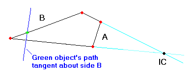
Figure 2.7) shows four bars, with the red dots representing pivots. The light blue lines are the line segments defined by the upper and lower pairs of pivots. The black dot at the intersection of the blue lines is the IC of side B and the adjacent arms moving in the reference frame of side A. The green mark represents an object (such as a wheel axle) on side B, with the dark blue line representing the object's path tangent as it moves about side A. The dark blue tangent is perpendicular to the line through the IC and green object.
Figure 2.7)
The idea is that for a small angle dq, the movements of our two arms produce the same paths as if component B and the arms were rotating about the IC.
WARNING! The IC is not a virtual pivot. In general, it is constantly in motion, unlike a pivot. In Figure 2.7), as side B moves about side A, the IC will constantly change, as will the dark blue line representing the green object's path tangent. Many errors in suspension theories result from ascribing to an IC the attributes of a pivot. The IC gives useful information, but only for an instant of time, thus the name, instant center. By contrast, a pivot might be referred to as a constant center.
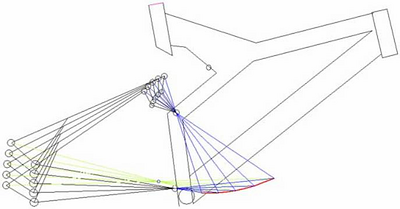
Figure 2.8) depicts a 4-bar suspension frame. The blue lines reveal various instant center positions for the rear suspension in the reference frame of the main triangle. The red curve plots the IC movement as the suspension moves through its travel. If the distance from the rear wheel axle to a fixed point remains almost constant through suspension travel, that is if the rear axle path is almost circular, then we can consider the fixed point a virtual pivot for the rear axle. The light green lines in Figure 2.8) reveal that a virtual pivot exists for the rear wheel axle, in the reference frame of the front triangle. Note that any virtual pivots will be unique to each point on the rear link. That is, the virtual pivot for the rear axle in this case will not be one for any other points on the rear link of significant distance from the rear axle. Other positions on the suspension may have virtual pivots, or they may not, since the distance deviation from any fixed points may be too large for useful approximations.