Figure 2.1)
Theory, text, illustrations, and editing by Ken Sasaki
4-bar path analysis by Peter Ejvinsson
Spanish Version translated by Antonio Osuna
Additional translation and edition for the web y José Rubio
Linkage suspension simulation by Gergely Kovacs
© Kenneth M. Sasaki 2001, all rights reserved
{The authors welcome the reposting or reprinting of this page or any part of it, so long as full credit is given to the authors}
Read this section if:
You want to verify for yourself the validity of the Path Analysis Main Assertions. and understand some of the related analysis in the fifth chapter, Flawed Theories and Bogus Marketing..
We strongly recommend at least reading the Reference Frames subsection. It will be very useful to understand this basic physical concept in later sections.
Skip this section (except the Reference Frames subsection) if:
You will accept the Path Analysis main assertions and are just interested in using PA to make conclusions about what suspensions can do and comparisons between various bikes.
This section is moderately difficult.
Fully understanding PA for bicycles requires some important concepts. We strongly suggest that those wishing to fully understand PA spend some time becoming familiar with these concepts as most erroneous suspension theories involve the neglect or misunderstanding of one or more of these, Center of Mass in particular.
In order to analyze any physical situation, we must create a reference frame. This is usually represented by of a set of coordinates in space, consisting of a mutually perpendicular set of lines, or axes, with common intersection. The place where the axes cross defines the origin, or zero point. We usually give names to each axis, such as x-axis or y-axis. Depending on the sort of information in which we are interested, coordinates could consist of one, two, three, or even more axes (though more then three axes depict more then the normal spatial dimensions and obviously cannot be pictured).
Often, we assign units of length along each axis. Each point in space lies along a line perpendicular to any given axis. Points may thus be defined by the set of numbers corresponding to the points along the axes through which these perpendicular lines pass. This system is called a rectangular coordinate system.
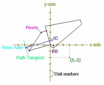
Figure 2.1) shows a 2-dimensional rectangular coordinate system. The axes are colored gold, with black unit markers indicating length (exactly what the length scale is in this case is not important, but usually it will be specified). A particular point (3,-2) is noted in the lower right quadrant. The x-coordinate is usually specified first, as it is here. A bicycle frame (and some other things that we dont need to worry about at this point) is pictured in the coordinate system, with the main pivot located at the origin.
Figure 2.1)
Reference frames may be defined by objects such as the earth or pieces of a bicycle frame. That is, we treat our coordinate system as if it were attached to the defining object. If the defining object is undergoing a linear acceleration, or has angular velocity (meaning it is rotating), then so will the reference frame. In this case, we call the reference frame non-inertial or accelerated.
If the coordinate system in Figure 2.1) were attached to the earth, then over time, the pictured frame (as part of a bicycle) would move with respect to the coordinate system. Since the earth is only undergoing very small accelerations we consider it (essentially) an inertial reference frame, for most practical purposes. If the coordinate system were attached to the main triangle, then the positions of other objects, such as the rear suspension members, would be defined by how they move about the main triangle. Since the main triangle is often undergoing significant accelerations, we consider it a non-inertial reference.
One thing to note is that in non-inertial reference frames, fictitious forces and torques can appear due to frame acceleration, the most well known of which is the centrifugal force of a rotating frame. If one is riding on one of those carnival rides that spin round and round, one feels as if there is a force (like gravity) pulling one out from the center of rotation and pinning one up against the constraining wall of the ride. This is the centrifugal force, which is only apparent.
The centrifugal force should not be confused with the centripetal force, which is the force of the wall causing one to deviate from a linear path and thus to rotate in a circle. The centripetal force is a real force. The centripetal force acts on the rider and points in, towards the center of rotation. The centrifugal force seems to act on the rider in a direction pointing out, away from the center of rotation.
Sometimes it is only important to define a reference by some object, but not important to define where the origin is located or any length scale. In this case, we may define the reference frame by naming some object, without specify anything else. For example, we may specify the reference frame of the bicycle main triangle. We do this when we want to consider how other objects move with respect to the object defining the reference, but dont care about particular distance scales and so forth.