
Figure 3.3)
B) Forces Between Linearly Constrained Particles.
Suspension performance is determined essentially by the relative movements of the PA-specified components. This is because the interfaces to the external world (the wheels) are identical in all bicycles for which there is a utility in comparison. We can thus do our analysis based entirely on these internal workings and neglect any external interactions (with the ground for example). This simplifies matters in that our analysis may involve less degrees of freedom.
As stated above, the specified bicycle components move along paths or one-dimensional spaces, assuming a reference frame attached to one of the supporting frame members. How each moves will depend on the sum of forces exerted between it and the other components in the system. So lets get some idea about how to treat objects moving along such paths by looking at some examples.
Suppose you have an x,y-axis. A particle, such as a marble, is restricted via some mechanism to move freely along the diagonal in the first quadrant. Any number of mechanisms could achieve the restricted movement. Now suppose there was a force F pushing on the particle in the x-direction. The equations of motion for the particle would involve F*cos (45°), that is, the direction of motion, but not the mechanism that restricts the degrees of freedom. Figure 3.3) shows the path, force, and force component along the path.
Figure 3.3)
Two particles move along paths relative to one another. If a force is induced between them, it will cause both particles to accelerate along their respective paths in the direction corresponding to the tangent component of the force along the path. Figure 3.4 A) shows this scenario.
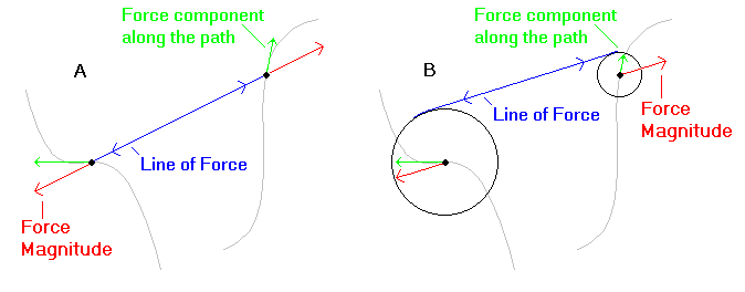
Figure 3.4)
Click to enlarge
Next consider two wheel axles that are restricted to travel along the same paths relative to one another as the particles in A), with axles at the same points. The same magnitude of force as in A) is exerted at the wheel edges. Figure 3.4 B) shows this situation.
Notice that the forces at the axles are in the direction of the force line between the cogs, which is different from the force direction on the particles in A). The forces are also of a different magnitude due to the inertia of the wheels. Particularly important is that these two forces at the axles are not co-linear. The components along the paths in B are in the same directions as those in A, but will generally be of different magnitudes due to both the differences in overall force direction and magnitude at the axles.
Now consider a particle such as a wheel axle that is restricted to travel along a particular path relative to other components in a mechanism (a main triangle for example). If forces are exerted by the other components on this axle, by whatever means, the axle will tend to move in the direction along its path that corresponds to the tangent component of the sum of the forces. The magnitude of the tangent component determines the motion of the axle. Similar considerations exist for the other components.
If one component's path in a mechanism is a function of another's path (in part or whole), then it does not matter how that relation is achieved; any mechanism will produce the same physical results. An example of such a functional relationship is that between a seat, handle bars, and bottom bracket, which define the main triangle. An essentially equivalent functional relationship is produced in GT's i-Drive.
As a result, if we want to consider performance in non-URTS, we need only examine the paths of the wheel axles, shock mounts, and brake, relative to the main triangle.
Figure 3.5) shows a rear axle path in relation to a main triangle for a non-URT. The gray lines denote several possible axle paths. The red line shows a line of force (through the chain). The green arrow shows the force induced at the wheel axle. The blue arrow shows the component of force along the wheel path at the axle.
Figure 3.5)
*** Here is a central point. In the small neighborhood around the axle denoted by the orange lines, the paths are identical. However, above the neighborhood they diverge wildly, one being circular and the others being of more radical curvature. We pictured this to emphasize that the path tangent is what counts at any moment in time. Other aspects of the paths have no bearing on what happens in our small neighborhood around the axle. In little neighborhoods around all points in a path, all suspensions with similar paths in that neighborhood behave similarly; in particular, they behave like some mono-pivot. When we shrink the neighborhoods to zero, we see that the tangent to the path determines suspension behavior at any point in the path. ***
This might seem strange if we consider mechanisms that produce paths with very different radii of curvature. But remember, it is what happens as the suspensions move away from the particular points on the paths with common tangents that make the situations differ. Greatly differing curvature will produce swiftly diverging physical situations.
The following example should allay concerns about whether or not the tangent can really contain all of the information necessary to evaluate a given situation regardless of path curvature.
Figures 3.6 A) and B) depict main triangles attached at different points to swing arms of different length. The paths that these swingarms produce are of different radii, but have the same path tangents at the initial locations of the base/swingarm pivots. We depict the mechanisms as being horizontal and viewed from above, so that we may start at equilibrium before a force F is applied to the main triangle. Without loss of generality, we choose the swing arms to be aligned along the y-axis.

Figure 3.6)
The force F may be applied at any point, in any direction. We chose to place it in such a way that the direction extends between the two frame/swingarm pivot locations in the different mechanisms because this is the situation that is most likely to cause concern.
Neglecting swingarm mass, we see that the x-component of F, Fx, will cause essentially identical initial movements of the main triangles in the two mechanisms, since this component is perpendicular to the swing arm. We also see that the y-component of F, Fy, will have the same lever arm about both of the pivots in both cases and thus also will cause identical initial movements of the main triangles. This means that the initial movements of both mechanisms due to the total force will be identical. The two situations will diverge as the swing arm/base pivot paths diverge outside of the initial little neighborhood around the initial positions. But in the initial positions, the physical situations are identical.
In reality, a swing arm as large as the one in Figure 3.6 A) might weigh a few pounds more then the one in B) (though the difference would still be less then 2% of the rider/main triangle mass). But such swing arms do not exist in real bikes. 4-bar frame members that can produce a path curvature similar to the one in A) do not weigh substantially more then ordinary mono-pivot swingarms and the mass tends to move in a generally similar fashion over all. So as we observed earlier, neglecting the masses of the suspension components is a good approximation in our analysis.