Figure 5.8)
Click to enlarge
It is a common misconception to think of chain tension in a URT (and i-Drive) swing arm as internal to the swing arm and thus not relevant to interactions between the swing arm and other bodies (the effect of gearing on acceleration is either forgotten, or held to be a different issue). Path Analysis tells us that this is false. But let us examine the situation rigorously for a URT to see if Path Analysis is really right. Since virtually the entire bike industry believes that internal chain tension does not matter in a URT, proving the idea wrong should be a convincing test for Path Analysis.
We will look at two separate arguments here. In both cases, we assume that the wheel is of reasonable mass.
We will first make an argument based on the simpler example of the pole and the wheel, and two of the concepts integral to Path Analysis, Nature Varies Smoothly (NVS). and the Coaxial Condition. This will give a simple, intuitive understanding that chain line due to gearing does matter in a URT. Unfortunately, we cannot think of a good intuitive explanation that even the same set of cogs will produce different results in different positions without resorting to (torque) = (force) ´ (lever arm).
We will then perform a rigorous force vector analysis.
Start with the pole and wheel situation depicted in Figure 2.5) of the Center of Mass section, mounted on a stand. Now it does not matter what we use to pull the string. We could pull the string using a crank, with the axle of the crank mounted on the stand, almost coaxial with the pole hinge, but just below it.
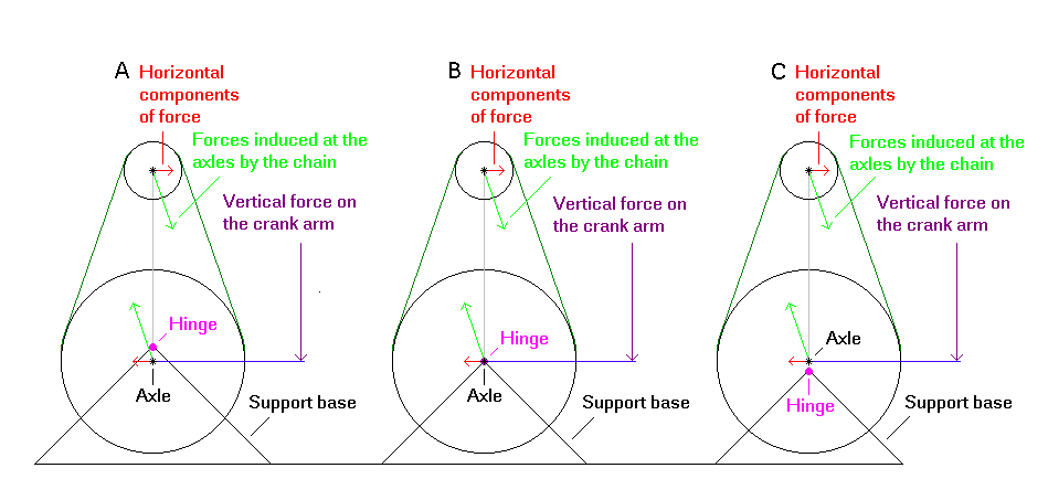
Let us assume that the crank cog is much bigger then the wheel, so that the pole will fall right very surely. Let us also have the pedals at the three o'clock/nine o'clock position and apply force to the pedals by an impulse straight down (this is done only for simplicity of analysis). See Figure 5.8 A) for the diagram.
Figure 5.8)
Click to enlarge
Now suppose we move the crank axle up so that it is coaxial with the pole hinge, but still mounted to the bench [see Figure 5.8 B)]. By NVS, nothing has changed. The pole will still fall to the right very surely.
We may now mount the crank to the pole, with the crank axle being coaxial to the pole hinge. But by the Coaxial Condition, again, nothing has changed. The pole will still fall right very surely.
If we now slide the crank slightly up the pole, by NVS, the pole will still fall right [see Figure 5.8 C)].
A similar argument can be made for a small crank pulling to the left - that is, a different gearing.
If gearing (chain line) and other "internal forces" did not matter, then the pole in Figure 5.8 C) would fall or not fall in the same manner regardless of the size of the crank cog. It should now be obvious that this makes little sense.
One can imagine that even a particular set of cogs will give different results depending on chain line, since the situation is likely to continue changing as we move the crank further up the pole. To see this explicitly, one must understand that (torque) = (force) ´ (lever arm). We get the total torque about the pivot by summing the contributions from the force at the wheel axle and the force at the crank axle times their respective lever arms. One can see by drawing a few pictures [see Figure 5.9)] that as we slide the crank up the pole, both the force components and the lever arms will change, and not in ways that will cancel.
Now that we have the basic idea, imagine a crank/main-pivot coaxial mono-pivot in any situation. By the Coaxial Condition, it does not matter whether we physically have a URT or a non-URT. The gearing will matter to the same extent in both cases (and everyone is already convinced that it matters in the non-URT case). As we move the crank off of the pivot, onto the rear triangle, the gearing effects will start out equal to those of a non-URT and change steadily. So we see that the same considerations that apply to the pole and wheel apply to a bicycle as well, and chain line matters in a URT.
We will now pursue a force vector analysis. Be mindful of the Center of Mass concept as we go through this, it applies both to the crank and the wheel. The results will be exactly the same as above.
Recall Figure 5.8 C).
What we have here is just a simple URT rear triangle hinged to the ground. There are two basic cases that we can have for the chain line. It can be vertical, or it can be non-vertical. The question is: If we apply an impulse to the right side pedal straight down (again, we choose this merely for simplicity), will the direction of the chain line influence whether or not the pole will fall and in which direction?
We need to look at all of the forces on the pole for the two cases.
The impulse at the pedal induces forces at the crank axle and at the pole/ground hinge, and it puts tension in the chain. The tension in the chain induces forces at the wheel and crank edges, which in turn induce forces at the wheel and crank axles.
In both cases, the vertical impulse at the pedal is felt at the crank axle as a vertical force. This, in turn is balanced by other vertical forces from the ground and the vertical components of the forces induced in the chain and wheel. That is, all of the vertical components of forces cancel. This should be pretty obvious, since we assume that the force of the pedal stroke does not dislodge the pole from the hinge or crush the pole. Now we must look at the non-vertical components.
We first analyze the forces for the case of a vertical chain line.
The chain tension is vertical and thus so are the induced forces at the crank and wheel axles. That is, all forces on the pole are vertical (there are no forces on the pole with horizontal components) and the pole will not fall.
But what about the case of a non-vertical chain line?
Here, the chain tension has a horizontal component and thus so will the induced forces at the crank and wheel axles. These are the only horizontal force components. The force at the crank axle will be opposite in direction to the force at the wheel axle and will generally not be of equal magnitude (due to the different inertias of the crank and wheel). These two forces also have different lever arms about the hinge at the bottom of the pole. As a result, a net torque will be induced around the hinge. The pole will fall in the direction of the force component at the wheel, assuming typical lever arms and a wheel of reasonable mass (without this assumption, we may actually get the opposite result). Again, all of the vertical forces cancel, as we expect.
We can see that even the same set of cogs will provide various results in various positions by moving a particular set around relative to the hinge and to each other. Figure 5.9) shows the forces on the pole for a particular set of cogs in a number of positions. Note the differences in the forces and lever arms in each of the cases, which make the torque about the hinge different.

Figure 5.9)
Click to enlarge
All this seems very strange at first. Here are some suggestions when thinking about this:
In our first example, the crank axle is almost coaxial to the pole/ground hinge, so the horizontal component of force at this point is largely cancelled by an (almost) equal and opposite force from the earth. That is, movement of the pole is restricted at this point. There is no such restriction of movement at the wheel axle, so that point will accelerate.
So we have established that chain line matters. We have used poles and wheels because they show very clearly how the forces apply. The results for particular chain lines will be different in a bicycle, but the same principles we have established here will apply, so the chain line will still matter in the same way.
Above all else, remember that when the pivot is close to the BB, the gearing (chain) situation in a URT will be very close to that of a non-URT.